
|
|
| Flt Control | 02.02.2003 |
|
|
The panel and his elements (Block 40/42 current, 50/52) |
|
|
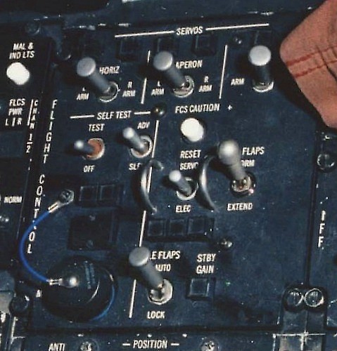
The panel and his elements (Block 25, 30/32, 40/42 old, MLU) |
|
|
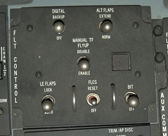
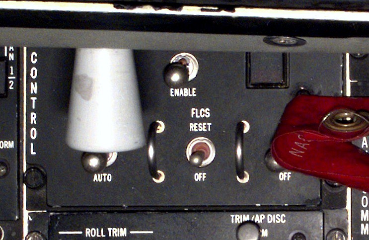
Pictures from the Flight Control Panel |
| The panel and his elements (Block 40/42 current, 50/52) |  |
| Element | Type | Position | Information |
|---|---|---|---|
| DIGITAL< | 2-Way switch (lever lock) |
BACKUP | Selects backup software program within the FLCC. |
| OFF | Normal position. | ||
| ALT FLAPS | 2-Way switch (lever lock) |
EXTEND | Trailing edge flaps (TEF) extend regardless of LG handle. |
| NORM | Trailing edge flaps (TEF) operation controlled by LG handle. | ||
| MANUAL TF FLYUP | 2-Way switch (lever lock) |
DISABLE | Fly-up protection not available in manual trailing flaps (TF). |
| ENABLE | Fly-up protection available in manual trailing flaps (TF) for TF or SWIM detected failure. | ||
| Status light | 2-Status light | RUN (green) |
FLCS BIT is running. |
| FAIL (red) |
Failure during the FLCS BIT. | ||
| LE FLAPS | 2-Way switch (lever lock) |
LOCK | Manually locks leading edge flaps (LEF) in present position and illuminates the FLCS warning light and FLCS LEF LOCK PFL. |
| AUTO | Leading edge flaps (LEF) are automatically controlled as a function of mach number, altitude and AOA. | ||
| FLCS | 2-Way switch (spring-loaded) (safety frame) |
RESET | Momentary position which performs servo or electronic reset of FLCS system failures. Resets FLCS warning light, CADC, FLCS FAULT and MASTER CAUTION lights and clears PFL's if fault is cleared. |
| OFF | Normal position | ||
| BIT | 2-Way switch | BIT | Commands build in test (BIT) if weight is on main LG and wheel speed is less than 28 knots ground speed. |
| OFF | Normal position |
| The panel and his elements (Block 25, 30/32, 40/42 old, MLU) | |
| Element | Type | Position | Information |
|---|---|---|---|
| L HORIZ tail servo | Status light | L (amber) | On, than indicates first failure of left horizontal ISA |
| R HORIZ tail servo | Status light | R (amber) | On, than indicates first failure of right horizontal ISA |
| HORIZ tail servo arm |
3-Way switch | L ARM | Arms servo monitor. Subsequent failure in left ISA will position left horizontal tail to neutral, will lock out roll commands to the right horizontal tail, and will illuminate the DUAL FC warning light. |
| Center | Normal position. | ||
| R ARM | Arms servo monitor. Subsequent failure in right ISA will position right horizontal tail to neutral, will lock out roll commands to the left horizontal tail, and will illuminate the DUAL FC warning light. | ||
| L FLAPERON servo | Status light | L (amber) | On, than indicates first failure of left flaperon ISA |
| R FLAPERON servo | Status light | R (amber) | On, than indicates first failure of right flaperon ISA |
| FLAPERON servo arm |
3-Way switch | L ARM | Arms servo monitor. Subsequent failure in left ISA will position left flaperon to neutral, will lock out trailing edge flaps (TEF) commands to both flaperons, and will illuminate the DUAL FC warning light. |
| Center | Normal position. | ||
| R ARM | Arms servo monitor. Subsequent failure in right ISA will position right flaperon to neutral, will lock out trailing edge flaps (TEF) commands to both flaperons, and will illuminate the DUAL FC warning light. | ||
| RUDDER servo | Status light | . (amber) | On, than indicates first failure of rudder ISA. |
| RUDDER servo arm |
2-Way switch | ARM | Arms servo monitor. Subsequent failure of ISA will position rudder tio neutral and will illuminate the DUAL FC warning light. |
| Not armed (center) | Normal position | ||
| SELF TEST | 2-Way switch | TEST | Indicates FLCS self-test. |
| OFF | Deenergizes self-test circuits. | ||
| ADV SLEW | 3-Way switch (spring-loaded) |
ADV | Advances the test program after a stop in test procedure. |
| Center | Normal position | ||
| SLEW | Advances the test sequence approximately one test number per second. | ||
| Test ADV | Status light | ADV (green) | Indicates a stop in test program wich requires manual advance. |
| Test MAL | Status light | MAL (amber) | If accompanied by a dot light, indicates a malfunction in the FLCS has been detected during self-test. |
| Test number | 7 Segment display | 2 Digits (green) |
Indicates step number of test being performed. This display has four dot lights around the numbers. The dot light in the left upper corner is spare. The "Rate Gyro Speed Detect Dot Light" in the right upper corner indicates rate gyro failure. The "ECA (=Electronic Component Assembly) Data Word Dot Light" in the lower left corner indicatesis failure in ECA. The "FLCC (=Flight Control Computer) Data Word Dot Light" in the lower right corner indicates failure in FLCC. |
| MON | Connector | ? | Test monitor receptacle. Connection for external test equipment. |
| FCS CAUTION RESET | Button | Push | Resets FLT CONT SYS caution light so that subsequent failures can be indicated and gives consent to allow SERVO reset. Also resets MASTER CAUTION light caused by FLT CONT SYS caution light illumination. Depressing FCS CAUTION RESET button in flight also causes the FLCS data recorder to store a frame of data. |
| SERVO ELEC RESET | 3-Way switch (spring-loaded) (safety frame) |
SERVO | Resets all failed ISA's when the FCS CAUTION RESET button is depressed simultaneously and illuminates five SERVO lights to test bulbs. |
| Center | Normal position | ||
| ELEC | Resets malfunctioning pitch, roll, yaw, ADC, LE FLAPS and CADC electronics. All resets FLT CONT SYS and MASTER CAUTION lights. | ||
| ALT FLAPS (lever lock) |
2-Way switch | NORM | Trailing edge flaps (TEF) operation controlled by LG handle. |
| EXTEND | Trailing edge flaps (TEF) extend regardless of LG handle. | ||
| Pitch | Status light | P (amber) | Indicated signal malfunction in pitch control electronics. |
| Roll | Status light | R (amber) | Indicated signal malfunction in roll control electronics. |
| Yaw | Status light | Y (amber) | Indicated signal malfunction in yaw control electronics. |
| LE FLAPS | 2-Way switch | AUTO | Leading edge flaps (LEF) are automatically controlled as a function of mach number, altitude and AOA. |
| LOCK | Locks leading edge flaps (LEF) in present position and illuminates LE FLAPS caution light. | ||
| STBY GAIN | Light | . (amber) | On, than indicates FLCS is operating on standby gains. |
| Pictures from the Flight Control Panel | |
| Flt Control | ||
 40/42c, 50/52 |
 40/42c, 50/52 |
 40/42c, 50/52 |
 25, 30/32, 40/42o, MLU |
 25, 30/32, 40/42o, MLU |
 25, 30/32, 40/42o, MLU |
|
|
(c) by Martin "Pegasus" Schmitt | |