
|
|
| SSC | 20.02.2010 |
|
|
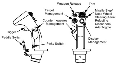
The Side Stick Controller with his functions |
|
|
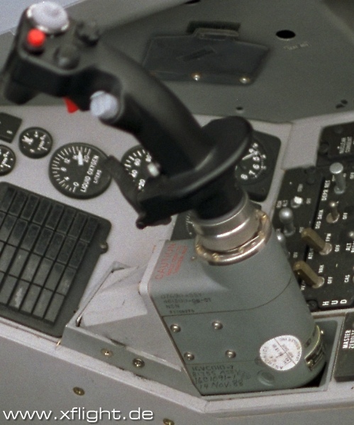
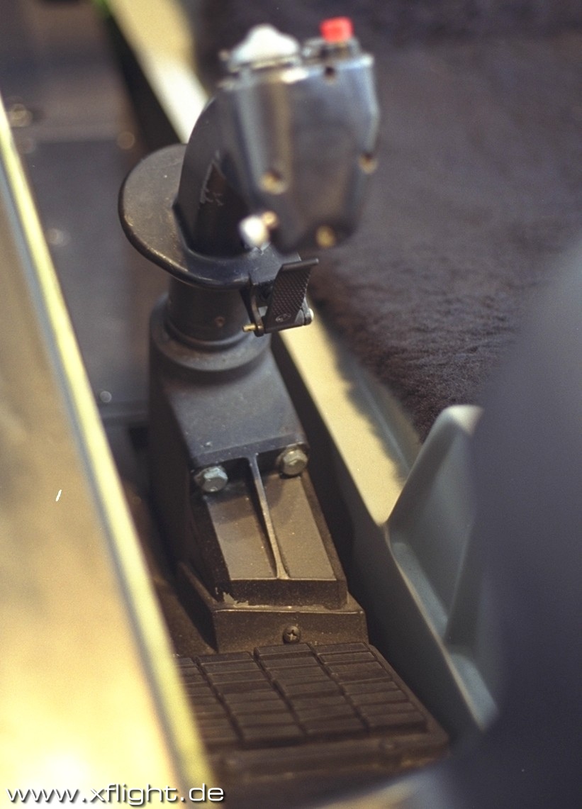
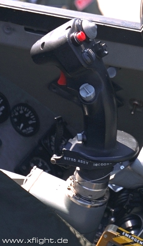
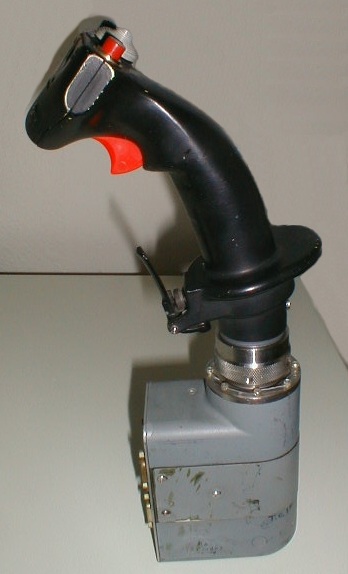
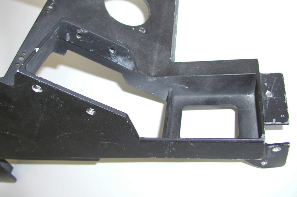
Pictures from the Side Stick Controller |
| The Side Stick Controller with his functions |  |
| Side Stick Controller |
|
| Control | Position | Function |
|---|---|---|
| NWS A/R DISC MSL STEP A-G TOGGLE |
depress |
NWS: On ground, activate or deactivate NWS. A/R DISC: Disconnects refuel boom latching. MSL STEP: In Air-to-Air modes, depressing MSL STEP (Missile Step) button selects the next available missile of the currently selected type. In EO modes, depressing MSL STEP button deselects the current EO missile and selects the prior-ity missile on the next station in aircraft priority. A-G TOGGLE: In Air-to-Ground bombing modes, depressing A-G TOGGLE deselects the current bombing mode and selects the next mode in rotary: CCRP, CCIP, and DTOS. A/G: The A/G TOGGLE mode does nothing when AGM-65's or AGM-119's are selected. A/A: When held for more than 0.5 seconds in A/A mode, toggles between short-range and medium-range missiles. |
| Trim | Fwd | Trims nosedown |
| Aft | Trims noseup | |
| Left | Trims left wing down | |
| Right | Trims left wing up | |
| Weapon Release | Depress |
Signals consent to FCC or SMS to initiate weapon release and operates HUD Camera
for 30 seconds when in AUTO. The WPN REL button provides consent for weapon
release (bombs, rockets, and missiles). This button can also be used for target
designation in the DTOS and EO visual modes.
The backup weapon release button you can find on the MISC panel named "ALT REL". |
| Target Management |
Fwd |
The TMS is a four-position, spring-loaded to center switch which controls target
designation and data for the radar, electro-optical weapons, and various
navigation/attack modes: RWS: Command SAM (aka bug target) SAM: Command STT or TTS (aka lock target) TWS: Command STT (aka lock target) ACM: Boresight scan ACM boresight; held: Slew radar beam A2G: Designate target |
| Aft |
STT/TTS: Command SAM (aka drop lock) SAM: Command TWS (aka drop bug) TWS: Command RWS SMT with no bug: Command RWS ACM: First press: inhibit radar. Second press: 10x60 scan |
|
| Left |
greater than 0.5 seconds: Command line-of-sight AIFF interrogation (less than 0.5 seconds) Command scanning AIFF interrogation TGP/EO: Toggle polarity HSD with datalink: Place CAS/SEAD datalink message on DED |
|
| Right |
less than 1 second, no bug: Bug closest target less than 1 second, bugged target: Step bug to next target lRWS, greater than 1 second: Command TWS lTWS/SMT, greater than 1 second: Command RWS ACM: 30x20 scan A2G: Cycle between sight points |
|
| Display Management |
Fwd |
The DMS is a four-position, spring-loaded to center switch used to control SOI
selection, format stepping, and the TWS AUTO/MAN rotary. If CCIP, CCIP rockets, STRF, DTOS, or EO-VIS is selected, the forward position moves SOI to the HUD. When LADD, EO PRE, or CCRP submode is selected along with IR or RP, the SOI designation will move to the HUD when the DMS is moved forward. When TWS is selected, TWS AUTO or MAN submode will be selected. |
| Aft | If the aft position is selected, the SOI moves to the MFD of the highest priority. Subsequent aft depression moves the SOI to the opposite MFD. | |
| Left | The left positions sequence MFD format to the next left format, respectively, skipping over any BLANK format. The order of format selection is from inside out. | |
| Right | The right positions sequence MFD format to the next right format, respectively, skipping over any BLANK format. The order of format selection is from inside out. | |
| Countermeasures Management |
Fwd |
CMS information and operation is CLASSIFIED. We can assume that it controls ECM
pod jamming and flare/chaff dispensing. In SP3 is the following setup is suggested:
navigation/attack modes: Run selected countermeasures program (1-4) |
| Aft | Provides consent for the jammer to automatically jam targets, and provides consent for the EWS to automatically drop chaff/flare if in SEMI or AUTO mode | |
| Left | Run countermeasures program 6 | |
| Right | Inhibits the jammer and removes consent for automatic chaff/flare dispensing | |
| Pinky Switch or Expand/FOV |
Depress | Successive depressions sequence through the available field-of-view (FOV) selections for the sensor/system mode being displayed on the DOI. For more details see Expand/FOV Switch. |
| Paddle Switch | Depress | Interrupts the autopilot while switch is depressed |
| Trigger | 1. detent | Starts operation of AVTR/CVTS with AUTO selected on AVTR power control switch and activates laser ranging if targeting pod is loaded. |
| 2. detent | Fires gun (if selected and armed), AVTR/CVTS operation continues, and consent for laser fire continues (camera operation continues for 30 seconds after trigger is released). |
| SOI | Options |
|---|---|
| FCR (ACM mode) or HUD | 30 x 20, 10 x 40 |
| FCR (TWS mode) | NORM, EXP |
| FCR (GM mode) | NORM, EXP, DBS1, DBS2 |
| FCR (SEA and GMT modes) | NORM, EXP |
| TGP (LGB/GBU) | WIDE FOV, NARROW FOV, EXP FOV |
| WPN (AGM-65D) | WIDE FOV, NARROW FOV |
| Pictures from the Side Stick Controller | |
| SSC | ||

|
|
|
|

|

|
|

|
|
|
|
(c) by Martin "Pegasus" Schmitt | |