
|
|
| Engine Start | 20.02.2010 |
|
|
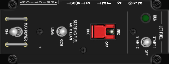
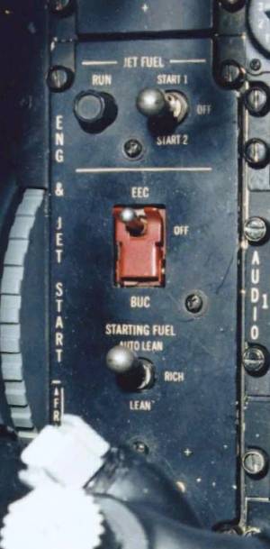
The panel and his elements (Pratt & Whitney F100) |
|
|
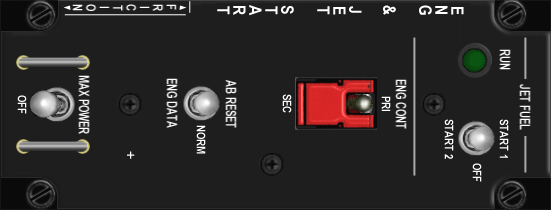
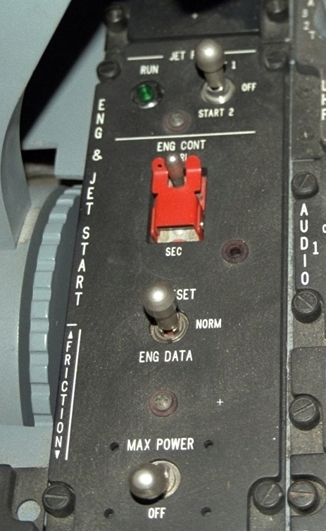
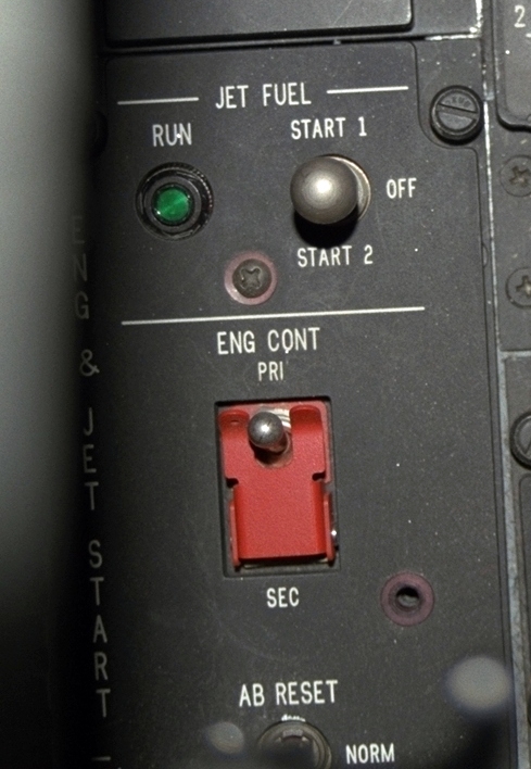
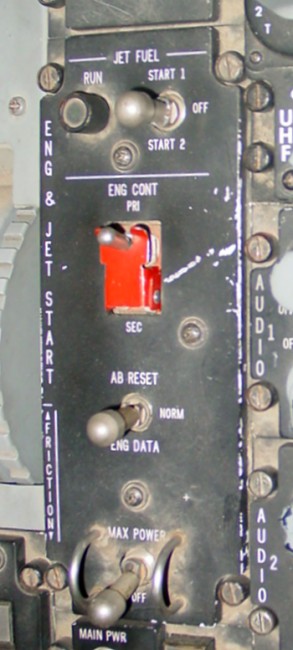
The panel and his elements (General Electric F110) |
|
|
Used engines |
|
|
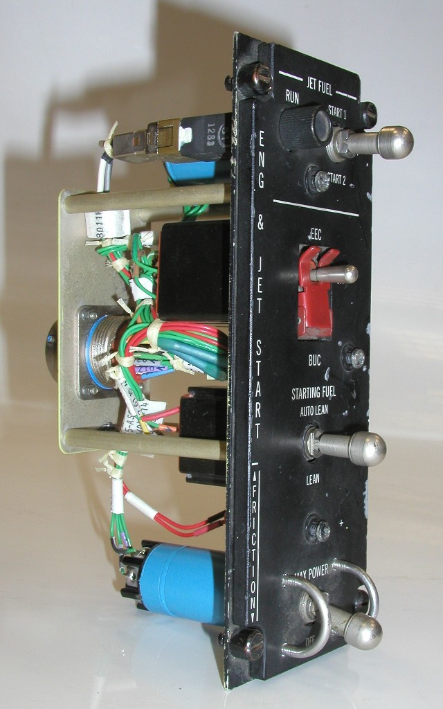
Pictures from the Engine/Jet Start Panel |
| The panel and his elements (Pratt & Whitney F100) |  |
| Element | Type | Position | Information |
|---|---|---|---|
| RUN | Light (green) |
Illuminates green within 30 seconds after initiating JFS start to indicate that the JFS has attained governed speed | |
| JFS | 3-Way switch | START 1 | Vents one of the hydraulic accumulators to the hydraulic start motor |
| OFF | Normal switch position. The JFS can be shut down at anytime by selecting OFF. The switch will return to OFF automatically during a normal ground start at 50 percent rpm. | ||
| START 2 | Vents booth hydraulic accumulators to the hydraulic start motor. This position is used for ground starts in extreme temperatures or after a start 1 failure. START 2 is also used for JFS-assisted airstarts. | ||
| EEC BUC | 3-Way switch (Safety bar) |
EEC (Safe) | EEC (electronic engine control) in operation (normal position) |
| OFF | EEC (electronic engine control) not in use (basic UFC operation) | ||
| BUC |
80: Transfer occurs when throttle is in OFF or above BUC IDLE. LESS 80: If rpm is above 52 percent and throttle position is at or above BUC IDLE, transfer to BUC occurs. If rpm is below 52 persent, transfer occurs regardless of throttle position. |
||
| STARTING FUEL | 3-Way switch | AUTO LEAN | If UFC (EEC ON or OFF), lean fuel flow is provided during the engine start cycle until 30 seconds after the main generator comes on the line. Fuel flow then increases by 100 pph (rich fuel flow). In BUC, rich starting fuel flow is provided. |
| RICH | Fuel flow is rich at all times | ||
| LEAN | Fuel flow is lean at all times | ||
| MAX POWER | 2-Way switch (Safety frame) |
MAX POWER | Delivers maximum thrust (VMAX) when at 1.1 mach or above and the throttle is at MAX AB |
| OFF | Normal (deenergized) position |
| The panel and his elements (General Electric F110) | |
| Element | Type | Position | Information |
|---|---|---|---|
| RUN | Light (green) |
Illuminates green within 30 seconds after initiating JFS start to indicate that the JFS has attained governed speed | |
| JFS | 3-Way switch | START 1 | Vents one of the hydraulic accumulators to the hydraulic start motor |
| OFF | Normal switch position. The JFS can be shut down at anytime by selecting OFF. The switch will return to OFF automatically during a normal ground start at 50 percent rpm. | ||
| START 2 | Vents booth hydraulic accumulators to the hydraulic start motor. This position is used for ground starts in extreme temperatures or after a start 1 failure. START 2 is also used for JFS-assisted airstarts. | ||
| ENG CONT | 2-Way switch (Safety bar) |
PRI (Safe) | The pimary engine control computer program is used when RPM is above 50% |
| SEC | The secondary engine control computer program is used at all RPMs | ||
| AB RESET | 3-Way switch | AB RESET | (momentary) Inoperative |
| NORM | Normal (deenergized) position | ||
| ENG DATA | (momentary) - Eight seconds of engine data is recorded to the EMSC (six seconds before the switch was engaged and 2 seconds after) | ||
| MAX POWER | 2-Way switch (Safety frame) |
MAX POWER | Does not do anything in the GE F110 aircraft |
| OFF | Does not do anything in the GE F110 aircraft |
| Used engines | |
| Block | Engine |
|---|---|
| MLU | F100-PW-220 |
| 20 | Pratt & Whitney F100-PW-200, F100-PW-220 (upgraded) |
| 25 | Pratt & Whitney F100-PW-200, F100-PW-220 (upgraded) |
| 30 | General Electric F110-GE-100 |
| 32 | Pratt & Whitney F100-PW-220 |
| 40 | General Electric F110-GE-100 |
| 42 | Pratt & Whitney F100-PW-220 |
| 50 | General Electric F110-GE-129 |
| 52 | Pratt & Whitney F100-PW-229 |
| Pictures from the Engine/Jet Start Panel | |
| Engine Start | |||
 PW F100 |
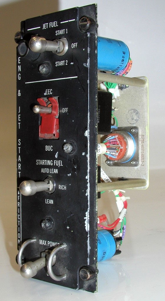 PW F100 |
 PW F100 |
 PW F100 |
 PW F100 |
 GE F110 |
 PW F100 |
 GE F110 |
|
|
(c) by Martin "Pegasus" Schmitt | |