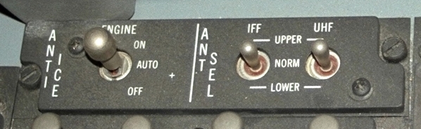
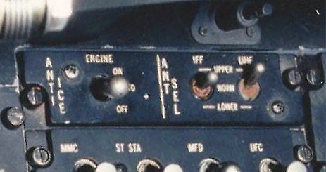
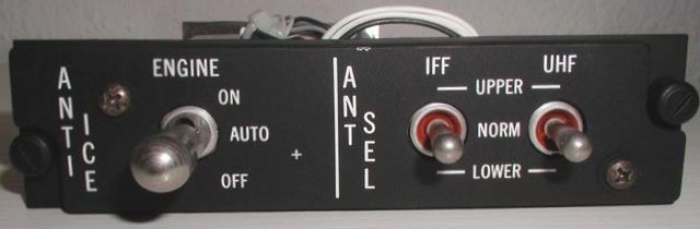
This panel consists of two panels, the Anti Ice Panel and the Antenna Selector Panel. Using the Anti Ice Panel
anti-icing functions are powered. If ice formation is detected, the INLET ICING warning light becomes lit on
the
Caution Panel. Using the Antenna Selector Panel, the pilot can
optimise the signals of IFF / UHF. The Anti Ice / Antenna Selector Panel is located at the
right console.
| Element |
Type |
Position |
Information |
| ENGINE |
3-Way switch |
ON |
Seventh-stage bleed air is directed to the fixed inlet guide vanes and nose cone. The
inlet struct electrical heater turns on.
|
| AUTO |
When engine icing is detected by the icing detector (automatic detection may not occur on the
ground or above 7 degrees AOA), seventh-stage bleed air is directed to the fixed inlet guide
vanes and nose cone and the inlet struct electrical heater turns on.
|
| OFF |
Electrical power closes the engine anti-ice valce (loss of power opens the valce). The
inlet struct heater is turned off.
|
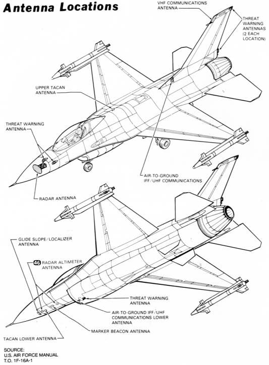
| IFF |
3-Way switch |
UPPER |
Select the upper IFF antenna |
| NORM |
Select automatically the IFF antenna that receiving the strongest signal |
| LOWER |
Select the lower IFF antenna |
| UHF |
3-Way switch |
UPPER |
Select the upper UHF antenna |
| NORM |
Select automatically the UHF antenna that receiving the strongest signal |
| LOWER |
Select the lower UHF antenna |
Note:
The showed panel drawing is a drawing with can be downloaded from my page
Documents,
plans and diagrams from the F-16.