A big problem appeared when I tried to build the instruments as realistic as possible. Where could a normal
person get in Europe exact pictures and drawings of the F-16`s instruments? I had to search for a long time
and right now I do not have all the informations I would like to have. Even though, using different help and
information. I was able to build the instruments quite realistic.
I had following information sources:
- pictures which I count take at the ILA (see pictures of ILA)
- drawings and pictures from the "LOCK ON No 2" magazine (ISBN 90-70932-03-2)
- pictures of the "Walk Around F-16 Fighting Falcon" (ISBN 0-89747-307-8)
- a cockpit model of the F-16 Block A 1:12 (ESCI Models)
Based on these informations I could get relative precise data about the instruments. As the different
instruments are built to be interchangeable, the size of one instrument could provide the dimensions of
another. Even though some compromises had to be made, as the FLCS and the Throttle of
Thrustmaster take more space and therefor panels placed
near the controls have less space.
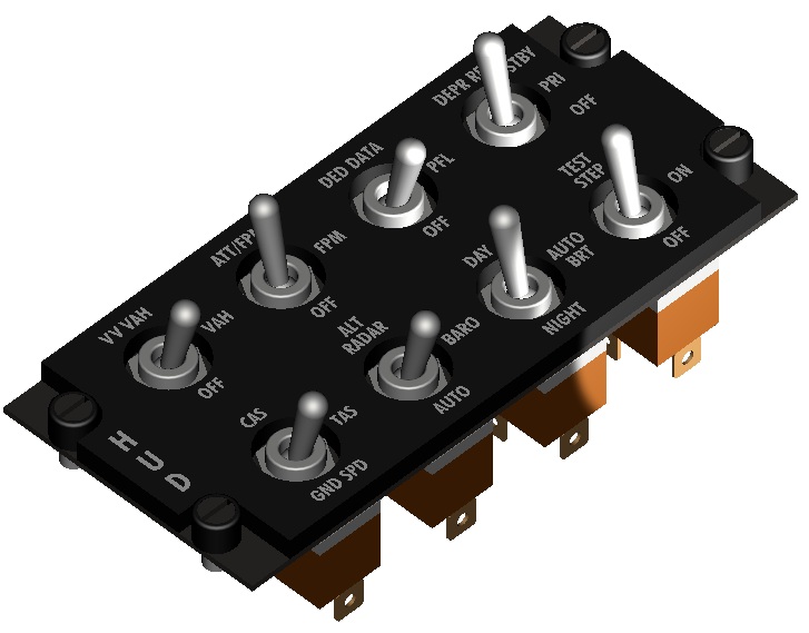
All instruments with switches/buttons - which I will call
"panels" in future,
are black-painted, and manufactured from1.5mm aluminum plate disks. The labels
consist of white "Rubbel" letters, which are used for labels of circuit boards
etc. The necessary switches, buttons and rotary knobs do not unfortunately always
resemble the originals. The rotary knobs were painted uniformly in grey (specifically
ACRYL resin spray " TS32 - HAZE GREY " of the company Tamiya, available in all
good model construction specialist shops). Original switches and buttons have the
company
EHC.
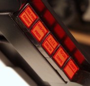
So far I like my panels quite good, but they still have a problem: they have not back-lighting, which is a big
handicap during night flights, as far as you don't want to use any spotlight or candles inside your cockpit ;-).
Therefore I have been designing new cheap but still realistic panels. So far I have experimented with
different materials like glass, plastic and now I have finally a solution that comes close to the real thing.
This design has the advantage, that the panels can be mounted on a metal basis. How are these special panels
built?
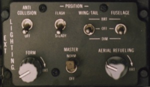
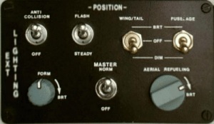
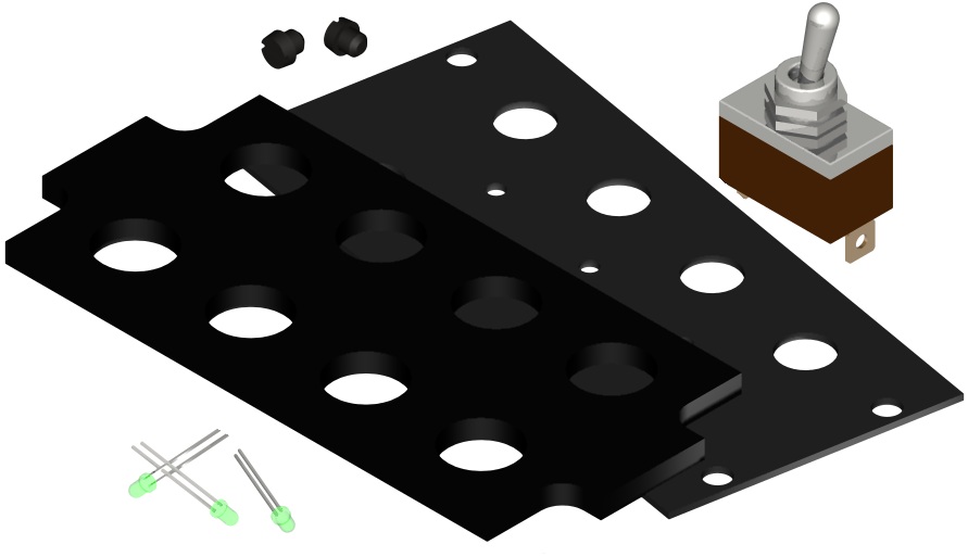
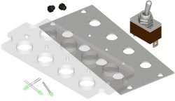
A black painted metall plate serves as basis for the switches to be installed. This plate is strong enough to
resist even extreme handling of the switches.
Onto the metal base a 5 mm acryl panel is screwed on. This is done from the bottom. The acryl panel has the
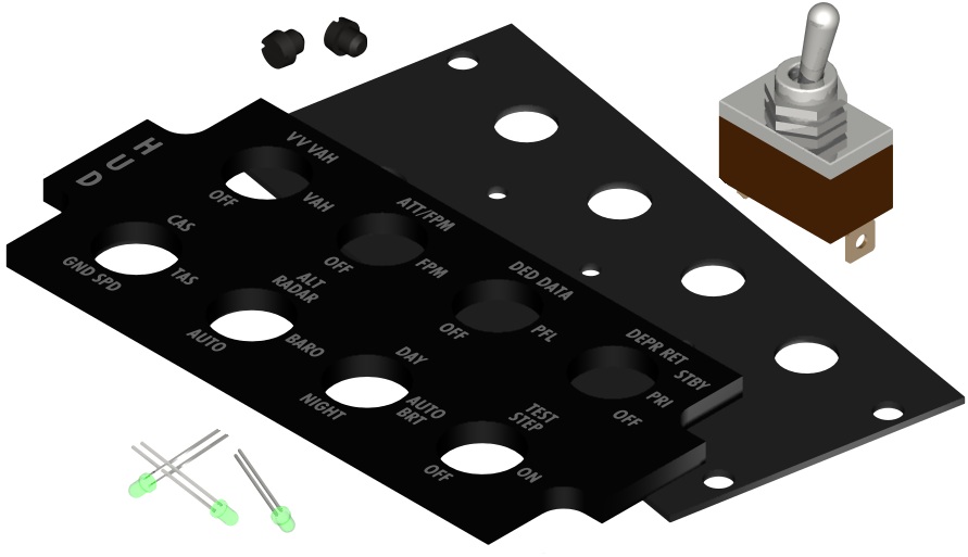
according drillings to hold the switches or required elements. The panel is painted with black enamel. The
labels are done by laser-burning and have a depth of about 1 mm. Another way is to engrave the labels with a
computerised engraver. There are many places where this labeling can be done.
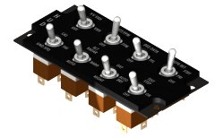
The lighting is achieved by several LED, which are installed at the backside with a depth of about 4 mm.
Lighting can be done using different LED colors (yellow, green or just white). The advantage of using LEDs is
that they are cheap, do not produce heat and require low ampere. Normally about 4 LEDs would be enough to
light any panel. The panels I saw, had a white light green shaded illumination. The advantage of using LEDs
instead of 5V light bulbs is obvious. LEDs are cheap, do not produce heat and require only low amperes. If you
have about 50 panels, these are facts to be considered.
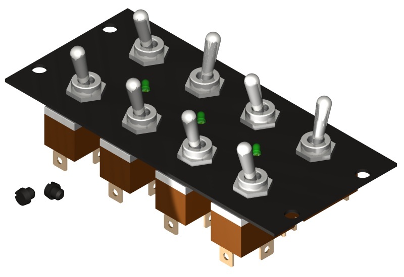
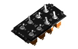
Connection is easily made using connectors at the lower side. One connector is used to power the LEDs and
another is used for powering the switches.
The panels are mounted onto the metal base using M4x4 metal screws. The original panels use bayonet screws,
but they are difficult to get. By the way the drilling for fitting the panels is 9,54 mm.
|
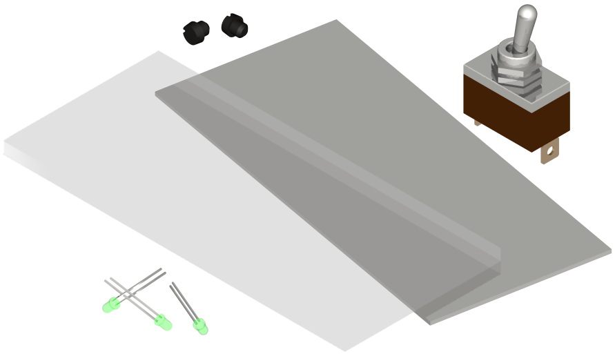
Procedure
|
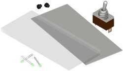
The basic panels...
|
...are drilled...
|
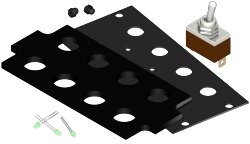
...black paint...
|
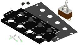
...labeling (laser or engraving).
|
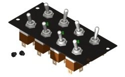
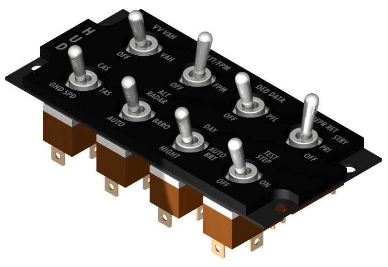
Fitting on the metal base...
|
...and ready!
|
Here with the corresponding screws
|
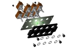
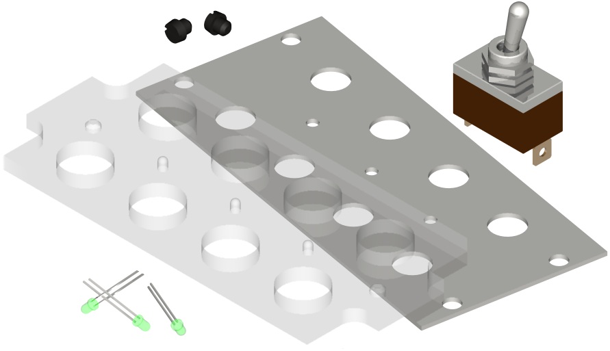
Diagram
|
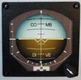
The instruments with displays (e.g. ALTO -, HSI or AOA displays) - I will call
in future
"displays" - consists of 3mm acrylic glass, which - with appropriate
marks taken off - were painted black (color spray "black silk matt" of the company
SPRAY COLOR). The displays are mockups from 1mm pasteboard, which - with prints
colored and cut out - were stuck one above the other in several layers, e.g. a
layer background, a layer of small pointers, a layer of large pointers, etc. Genuine
instruments were too expensive for me, and are likewise connected to the computer
only at immense expense.
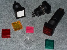
I have been asked many times, how I have installed the warning-lights on the glare-shield. Well in some
electronic shops (here in Germany
Conrad-Electronik for example) have square
lights of about 18 x 18 mm and 24 x 18mm (for the master caution). Normaly they are sold with 4 covers, each a
different color (yellow, green ,red and white). The light bulb that is included requires 24 VDC and can be
replaced by a LED. The label is made wit a CAD program and printed on plastic foil. The powering of the
warning lights is done by the
32 point output modul of the EPIC card.
That simple.